To understand the main idea of mirrored projetivity, it seems helpfull, to remember the story of the birth of interference networks.
In the end of september 1992 first fog banks come nightly. When I remember well, one night in thick fog many people had been killed against an coach-ride accident. One technical idea to avoid this is the development of an imaging pulse radar for trucks and buses.
The old principle of a rotating radar with a single receiver and transmitter is not suitable for imaging systems. Instead of a rotary antenna, four fixed antennas are to use, to mount antennas at the front of the bus or truck.
The idea: To generate an image, four incoming antenna data streams could be directed in opposite directions across a detector array, Fig.1. As simple as the idea seems, its implementation appears complex.
If we want to resolve the image to 1 centimeter, we reach the frequency range above 30 GHz. This rules out circuit board solutions; but developing an interating circuit would cost hundreds of thousands of marks.
Remark: c = s/t = s·f; f = c/s = 300,000 km/s / 0.01 m = 30 GHz; 1/f = 33ps
Research had shown that calculating such a system is not easy. I lacked the tools to solve equations in an acceptable time. (This later led to PSI tools for simulating multi-channel interference systems.)
So I read books about optics and wave interference [1] as books about radar systems [2], [3] to try to understand partially the physics and mathematics of pulspropagating interference systems. (It was the point to create PSI-Tools later to verify interference systems with lots of channels).
Fig.1: a) Sketch of the Receiver for (pulse-) Radar-images from Sept. 29, 1992. c) Single detector cell. (PhC: Phase comparator as 4-input AND, Ax: Antenna above O, down U, left L, right R). Each phase comparator should drive an indicator LED. Since a mirrored projection is received, the antenna cables for up/down and left/right would need to be swapped. Since a (doubly) mirrored projection is received, the antenna cables for up/down and left/right would have to be swapped.
After some consideration, a particular result of such interference patterns seemed to be predictable: The only selectable location of interference is the point of equal delays on all possible signal ways. Only in this point of interference it is possible, to receive a highest excitement for example with multiplying AND-like gates (PhC).
This point, however, lies diagonally opposite the origin. Consequently, a mirror image is created - more precisely, an image is mirrored with respect to the spatial dimension d. A two-dimensional image is therefore mirrored twice, an n-dimensional image n-fold.
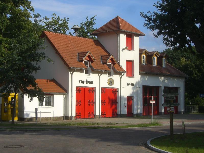
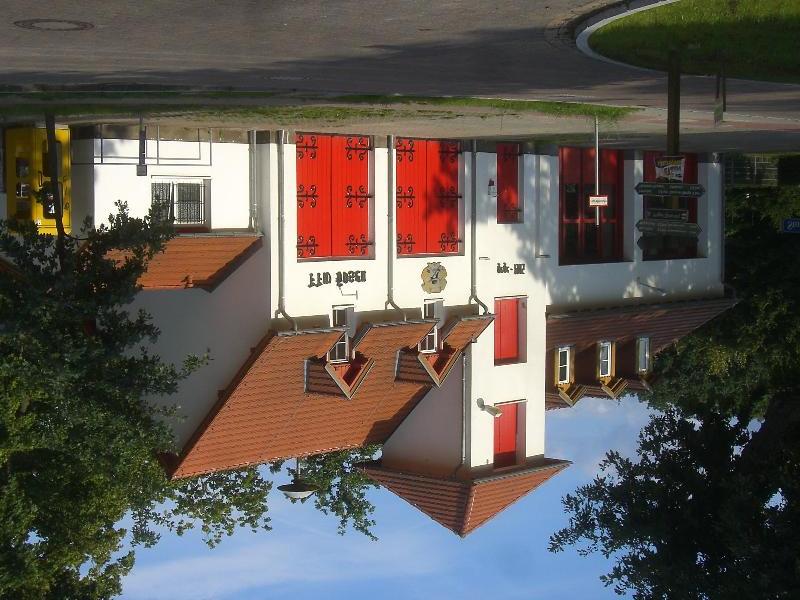

Fig. 2: On the double mirroring of interference projection: from left to right, original; top/bottom reversed; top/bottom and left/right reversed.
As more circuits were verified, as more three impression were fixed:
While recherching books about neuroanatomy, I found a paper about mirrored, topographic maps in the human brain, for example Penfields so called 'Homunculus'. It appeared as a pure coincidence, that this virtual mirrored RADAR-images reproduced this behavior.
Fig.3: One-dimensional interference projection. An excitement at the side G generates an mirrored interference position at the other side M (circuit created in october 1992). Note the main differences to electric circuits: wires L have different tasks. Wires in interference schemes are supposed to be without attenuation, but they have a transmission speed. They are not nodes, constructed to carry currents or to drive loads. Comparable to nerves they symbolize the directed flow of time-functions from and to different points with definitive speeds or delays.
Developing the "Bio-Interface" (PSI-Tools), we were able to inspect interference phaenomena in simulation since August 1994. The main interest are bio-neural informatics: theory shows, that researches in this field need multi-channel data streams and interference theory in general. In this field, interference calculaions are not to avoid to get knowledge about neural communication.
In the field of industrial usability it is possible to simulate new ultrasonic devices with very better imaging possibilities for purposes of medical and material imaging.
For free field applications in air the interference assistent is useable for loudness-localizations in the fields: motor inspection/machinery-inspection; loudness landcard generation etc.. Electrical field applications are possible to develope Radar imaging systems. Last not least for geological and astronomical research interference theories appear usefull to develope better antenna arragements to improve measurement possibilities for noisy, small and far signals.
I realized: Nothing in nature is without reason. Even as a virtual radar image, the homunculus would appear mirrored. Even as Radar-images biological maps are topographic. And even as (virtual, pulsed) Radar-images, the nature uses pulses in a definitive relation to the transmitting speeds. Also the properties between pulse-length and pulse-speed and circuit geometries (geometric wave length) are comparable.
G. Heinz
[1] Alonso M., Finn, E.J.: Physics. Addison-Wesley Pub. Company 1970
[2] Baur, Erwin; Einführung in die Radartechnik. B.G. Teubner, Stuttgart, 1985
[3] Skolnik, M. I.; Introduction to Radar Systems. McGraw-Hill Book Company Inc., 1962
e-Mail: info@gheinz.de
Visitors since Dez. 6, 2021:
file created 08:04 Jan. 26, 1996
last revised 08:05 Jan. 26, 1996
stylesheet added and redesign Jan. 30, 2024
revised July 30, 2025
Fig.2 added Nov. 2025